ONE FACILITY · ONE LOOP
PROTOTYPING & SCALE-UP
The Engineering Feedback Loop
Hardware development is never linear. Our loop of design, build, test and analysis ensures that the measurement data from every physical prototype feeds into the next iteration. Battery efficiency and safety improve with every pass.
01 / DESIGN
Cell Selection & Pack Modelling
Cell characterisation and selection; thermal and mechanical design of the pack.
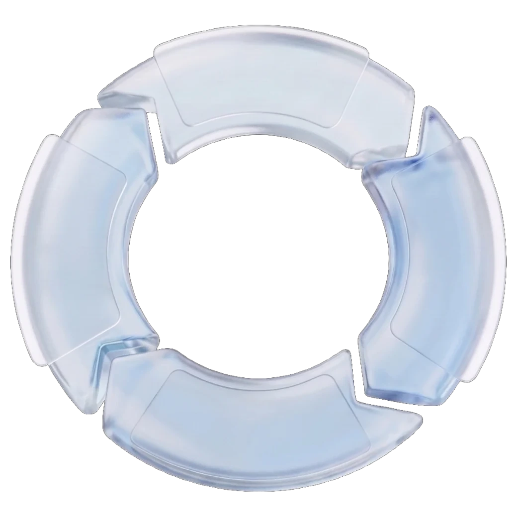
Every battery starts with its material
Cell design and material strategy are where every battery cell and pack begins. We don't manufacture cells ourselves: we select them, characterise them and build our prototypes around their properties.
The cell takes its place
This is where our prototyping begins. The qualified cell seats into the pack, and housing, contacts and compression are engineered around the cell, not the other way round.
Built to be tested
Modules are set into the tray in pairs, with pressure plates and a load-bearing spine. Each build step is a test step: what goes together must survive together.
Sealed and signed off
The enclosure closes over the finished system. What leaves this bench is a sealed KE-TEC compound, documented from particle to lid.
And it drives
The compound is installed in the vehicle it was engineered for. The story that started at a particle ends on the road.
Build Your Prototype With Us
Contact our engineering team to scope your validation programme.
Straight answers, before you write to us
Can you build the prototype module as well as test it, or do I need a separate build partner?
Build and test happen in the same facility. We build, modify and abuse-test prototype modules under one roof, from a single first sample to a qualified small series, with instrumentation and teardown alongside. The point is compressing validation cycles that traditionally span multiple suppliers: nothing waits in a courier van between iterations.
How do you weld cell interconnects on prototype modules?
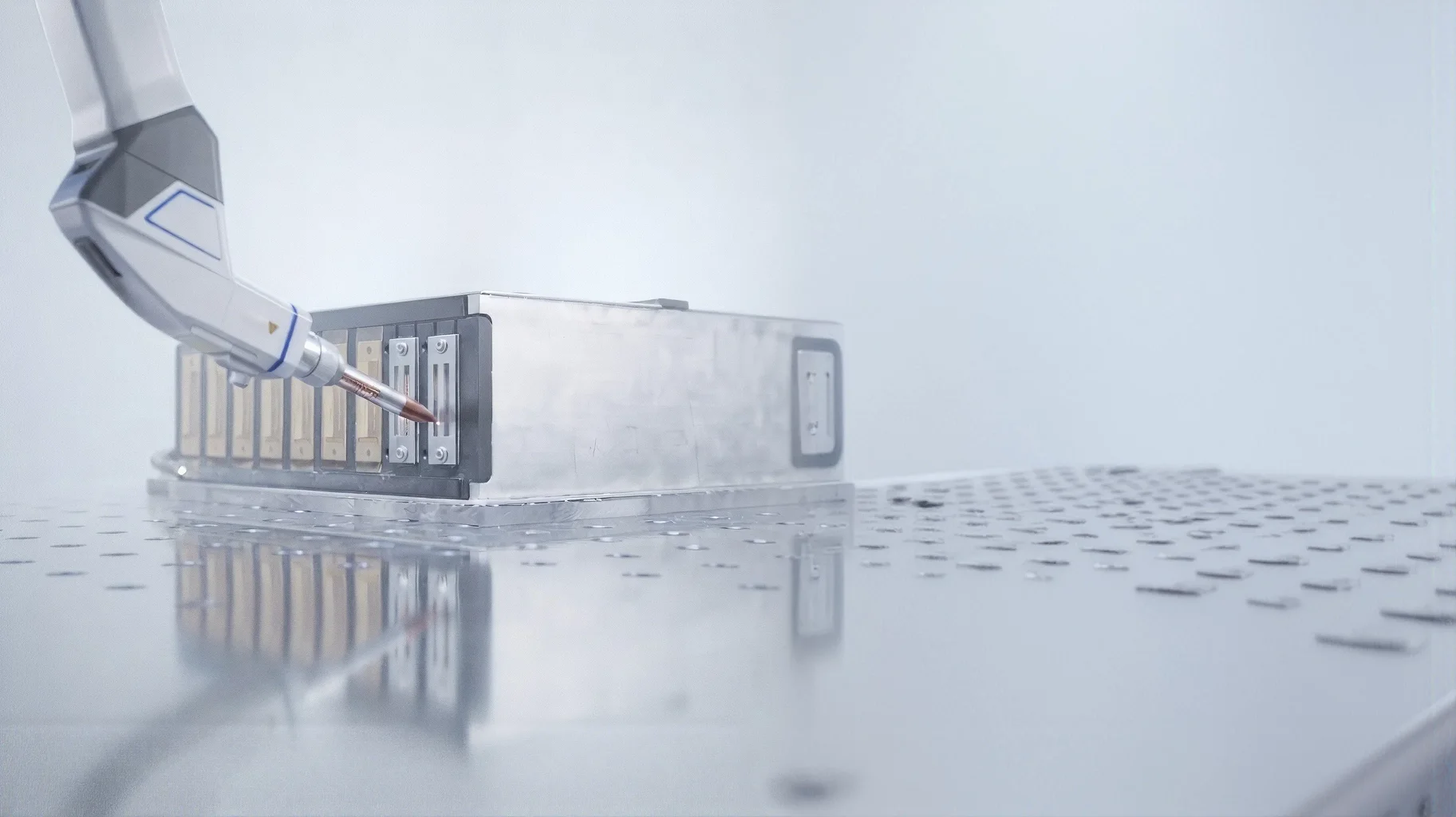
With a 1,200 W laser, handheld or mounted on a six-axis cobot. Deep-penetration laser welding produces low-resistance Al-Cu bi-metal joints unattainable with conventional TIG or MIG, and a heat-affected zone under 0.3 mm protects cell separators when welding directly on assembled modules.
Can you machine pack housings and fixtures in-house, or does that go to a supplier?
In-house, on a DMG MORI three-axis vertical machining centre with 550 x 550 x 510 mm travels and a 600 kg table load. Pack housings, cold plates, busbars and assembly fixtures are milled on site, so a revised bracket or cooling plate goes straight back to the bench instead of waiting on an external supplier.
What does a pack development programme look like from cell selection to a working prototype?
Four stages. Cell selection and characterisation first: impedance spectroscopy, capacity cycling and performance analysis against your requirements. Then structural integration, with cells interconnected by laser welding. Then thermal pathway design, comparing cooling concepts for weight, cost and thermal efficiency. Finally a custom BMS, tailored to your voltage configuration, currents, form factor and communication protocols.
How does test data feed back into the next build iteration?
As a closed loop. Cell selection and pack modelling lead into mechanical integration, then lifetime cycling and abuse testing: nail penetration, thermal shock, short circuit. Pack performance analysis follows, tracking shifts in electrical metrics such as DCIR and EIS alongside cell teardown, and those findings feed directly into the next design revision.
Do you cover the electronics side of a prototype, such as the BMS board and temperature sensing?
Yes. Multi-layer PCBs and power stages for high-current battery systems are designed and tested entirely in-house, with flexible PCBs used where boards must endure heat and mechanical stress. Customer-specific flexible NTC foils handle temperature sensing, and housings are 3D printed in heat-resistant materials.